Looking back over the past 6 weeks, i believe that our group has struggled to work well together. It seemed to be lack of communication from other group members which made things extremely difficult to get done. In order to help this we decided to create a joint "DropBox" account where we can all upload files so that we could get immediate feedback from each other. Also to aid the communication between us as a group I took created a Facebook thread, this made easier to keep in touch. We had lost contact with 2 particular group members for a couple of weeks at one point and realised that the remaining 3 of us would have to get their share of the project completed. Shortly as we started to do so, we heard from the other members. This was not ideal. Since then everyone had been attending lectures and cracking on with their work. This did not change my opinion of certain member not pulling thier weight for the project though.
From the gantt chart its possible to see who did what activity and when. I felt that this was a very good way of keeping to a structure and sticking to deadlines!
The final animation i am extremely pleased with. During our presentation we recieved great feedback from both Elli and tutors, this made me personally feel like i had achieved what had been asked of me and the group. This does go to show that if the other members of the group pulled their weight we would have been able to produce something much, much better.
Friday, 10 December 2010
Evaluation of Project Head
Reflecting back on my mark i previously received i was happy with that, as i was expecting something of a lower score. With the model now improved i feel that i could potentially reach i score i would be extremely happy with.
What went well and what didnt go well?
As previously said i was covering ground very quickly, until i accidently grouped all the modifiers together and ended up with a head that was turbosmoothed and symetrical. This was not ideal as this task required completing work on only one half of the face. This understandably prolonged my speed at which to complete the project. This made texturing rushed and not completed to satisfactory level by my standard.
Overall i feel that the ear is looking extremely good now it has been recreated. Also the Unwrap UVW modifier worked very well. This is an area which needs time spent carefully on it, although this was made even longer by grouping the model together. Ideally i would have liked the head to have looked more realistic, but i still believe it is possible to realise it is me...so thats a plus side i guess :)
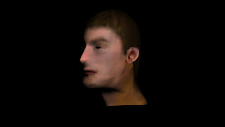
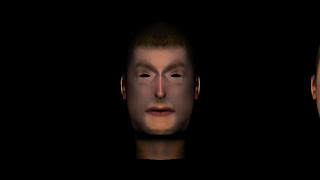
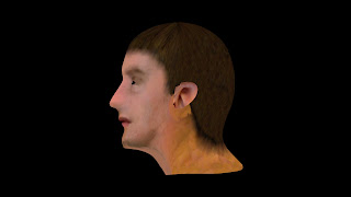
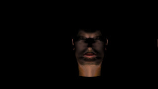
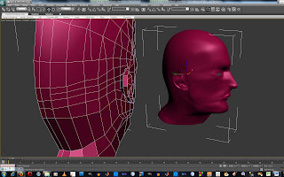
Final renders of my model
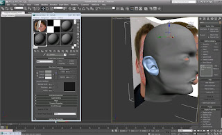
With the ear now attached i had to completely re do the material texture for my head. I was not completely happy with the outcome, as i made a massive mistake when modelling. I accidently grouped everything together on the original model and was un able to re open the previous model. This made editing, aminating and creating the texture extremely difficult.
I have used an omni light in a couple of the photos to give the render another effect. As you can see the texture over the ear is not the greatest, but still this is an improvment on the previous model as i was able to attach it this time.
I have used an omni light in a couple of the photos to give the render another effect. As you can see the texture over the ear is not the greatest, but still this is an improvment on the previous model as i was able to attach it this time.


Wednesday, 8 December 2010
Amendments to the head
When previously modelling my head i had able to attach the ear to the model. Now i have been able to do this the result make the model look so much better.
I re-do the topology for the ear. This time i counted out the amount of sides i had to fit the ear to the head. In this case it was 12, I was able to use this number and create 12 edges over my ear topology. Once the ear had been created in the same way that the head had been (using the line tool, and welding the verticies together) I then had the tricky task of joining it to the head. As the snap tool was bugging out, i had to roughly match up the verticies i wanted to weld together by freehand.
With quite a bit of time used manipulating the ear and joining up the verticies, i feel that is was worth it. This feature adds so much more realism to the look of the model.

Friday, 3 December 2010
Rendering and outputs
The final animation will be rendered in HD (720p). The following specification is what we have decided to use:
What did I have to render?
As we have 5 members of the group we decided to split up the animating and rendering between us. I decided to animate and render the follwing scenes:
What are the next steps to take?
Once all the group members have got their movies created we will be able to put them all into Adobe PremierPro and then we can start to edit each scene and create our final product, which will be shown to Ellie Constantatou on Wednesday 8th December.
- Width - 1280
- Height - 720
- AVI Video Clip
- Uncompressed & Compressed format
What did I have to render?
As we have 5 members of the group we decided to split up the animating and rendering between us. I decided to animate and render the follwing scenes:
- Opening scene
- Paintballing scene
- Zipline scene
- Ending scene
What are the next steps to take?
Once all the group members have got their movies created we will be able to put them all into Adobe PremierPro and then we can start to edit each scene and create our final product, which will be shown to Ellie Constantatou on Wednesday 8th December.
Wednesday, 1 December 2010
SuperSpray

In order to create the paint balling scene (that would be filmed in first person) I had to think of a way to manipulate this using a white background. I came across the idea of creating mist from the humans mouth. Using this technique along with heavy breathing, and other sound effects it would create a very good representation.
As I had no previous experience of creating mist I searched the Internet for tutorials until finally I found one for cigarette smoke. I used this up to a point where I needed to change the values to suit myself.
Wind and drag modifiers were added to give realism and direction to the mist. As you can see from the screen shot above, there are many bursts of mist (one for each breath). Initially it was difficult to select an appropriate particle count, but after trial and error within the render area I was able to select a count of approx 90. Looking at the screen shot below the sections outlined in red are the one that have a noticable affect when their values change.

I am adamant that this scene was the hardest to create, but I am also very pleased with the outcome of it. One reason being because I have learnt an extremely useful technique which i can take on to further development in the future.
I also added in paint balls coming from behind the person, this adds to the environment that is being portrayed to the audience.
Sunday, 28 November 2010
Animating the first scene

Looking at the gantt chart it was up to me to complete the animation for the opening scene. This was a fairly simple procedure as it was a case of getting the timings right for the trees popping up, the text dropping from the sky and the camera.
The screen shot shows that i have used the curve editor in order to create a realistic falling affect for the text. I also added a squashing effect of the text when it hits the ground, it then expands once the built up energy has been released.
The next step for me would be to create the kayak scene, for this i will use the rigged person.
Sunday, 21 November 2010
Modelling the rock climbing and abseiling wall
This was a very simple task that included a box, with a series of different and odd looking shapes placed over it. The image below is the wall at this moment in time. It could be edited at a later date in order to meet specific needs.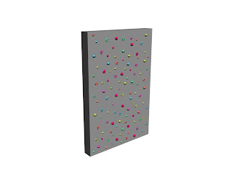
Modelling the kayak and paddle
As i had already completed my part of the modelling duties i put my hands up to giving others in the group a hand. Therefore i took up the task of creating the kayak and paddle. I used reference planes and similar tasks to which i used in the head modelling project.
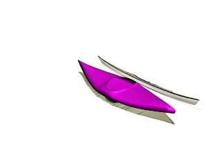
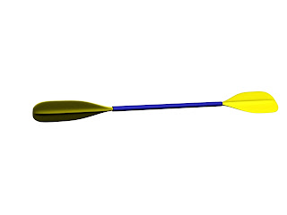
Below are the finished models without textures.
Wednesday, 10 November 2010
Wednesday 10th November Meeting
Members present: Lee, Karim, Ross, Aaron and Andrew
Room: Sawyers 303A
Time: 0900
- How we will meet the marking criteria
- Where we are with our tasks (see gantt chart)
- What are the next steps for us to take as a group
The gantt chart will be updated next week once we know what tasks we will need to get done.
Monday, 8 November 2010
Modelling the different activities of "Active Essex"
As you can see by looking at the group blog it was decided that the best way for this this project to take steps forward were to split up the tasks into smaller sections so that individually we could produce different models.
My tasks were to produce both the rock climbing and abseiling scenes. I will obviously be using Autodesk 3Ds Max to create this, but i will also be using images, that we took on Friday at the outdoor activity centre based in Harlow as references.
Friday, 22 October 2010
What went well? What didn't go well?
Throughout this project i have learnt a vast amount of information and techniques within 3Ds max. My aim is to keep using this skills to benefit me in life. I feel that my topology - quadrant relationship was very good, as i am very happy with the overall structure of my model. I was particularly happy with the structure of my mouth and nose. These areas were quite fiddly to get correct. I am also happy with my UVW wrapping skills throughout. I was able to flatten my face so that i could have a good base layer for creating the skin image.
Now on to the areas which didn't go so well. These are from the middle of week 3 onwards. It all started from the ears section. I found it extremely difficult to sew it onto my head. Therefore i have just used the JPEG image of my ear to represent where it should be on the final model. This does let the image down somewhat. I am also not happy with the skin image i created in photoshop. I admit i did not spend enough time on this and it was rushed.
From this extensive project i have learnt that i need to keep to a serious time management structure in order to succeed in the future. On a positive note i do strongly believe that my modelling skills have improved dramatically.


Week 5 creating and fitting the eye
For the eye all i did was create a sphere, and applied a material to it of an image of a an eye. I had to tweek the tiling slightly in order for the image to only fill half of the sphere. Below is an image of the eye.
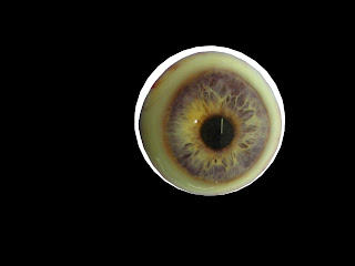
When fitting the eyes to the head i realised that the sockets were not completely spherical, this gave me a problem of not being able to easily fit the eye into the socket itself.

When fitting the eyes to the head i realised that the sockets were not completely spherical, this gave me a problem of not being able to easily fit the eye into the socket itself.
Week 5 creating and applying the skin
Using photoshop and the uvw render map i was able to create a flat image of my face. This was then used for the bitmap for the skin in 3Ds Max.
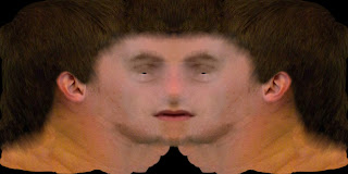
Along with the above image i also used a high pass feature (within photoshop). This brought out all the definitions within my face and was used with the bump tool in the material editor section.

Along with the above image i also used a high pass feature (within photoshop). This brought out all the definitions within my face and was used with the bump tool in the material editor section.
Thursday, 21 October 2010
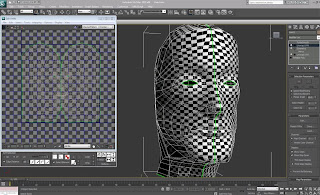
Week 4 Unwrap UVW Modifier
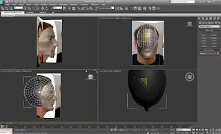
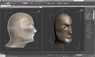
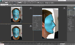
This is the stage where i prepare the model ready for my image to be placed upon it. As for the entire project i was only working on 1 half of the model as i can apply a symmetry modifier afterwards in order to create a copy.
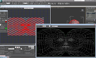
I started off by applying a checkered pattern to the model. Using this i could see what areas were stretched. Once the UVW modifier was applied the quadrants needed to be layed out flat. No edges could be overlapping. The different types of the relax tool were used to space out the quadrants around the eye, nose and mouth.
Once the symmetry modifier was applied, i then welded the verticies that met one another, together. The image below shows the final version of this.
I started off by applying a checkered pattern to the model. Using this i could see what areas were stretched. Once the UVW modifier was applied the quadrants needed to be layed out flat. No edges could be overlapping. The different types of the relax tool were used to space out the quadrants around the eye, nose and mouth.

Once the symmetry modifier was applied, i then welded the verticies that met one another, together. The image below shows the final version of this.

Modelling the ears
In order to create the ears, i had to draw on the topology in photoshop, and create a mesh in the same way i did for the head. Once this was created i pulled the vertices around to their correct positions. Different techniques such as insert and extrude were used to show the canals/tubing of the ears.
.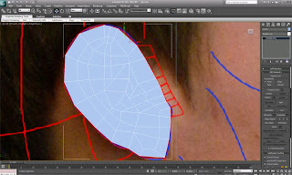
For the time being i have decided to leave the ears as they are (they are in an un-finished stage) as i dont want to lose marks by not being able to complete the uvw mapping etc.
I also tried sewing my ear onto my head, but this created many more disruptions and obsiticals for me to overcome, so i decided that it is for the best to leave the ears off the model at the moment.
.


For the time being i have decided to leave the ears as they are (they are in an un-finished stage) as i dont want to lose marks by not being able to complete the uvw mapping etc.
I also tried sewing my ear onto my head, but this created many more disruptions and obsiticals for me to overcome, so i decided that it is for the best to leave the ears off the model at the moment.
Tuesday, 19 October 2010
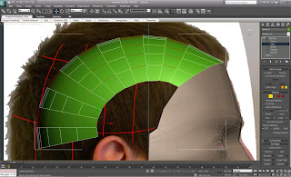
Week 3 Modelling the back of the head and ears
I started off with a sphere to resemble the rear of my head, this was manipulated and transformed by using the rotate and scale tools. A rotation of 90 degrees clockwise was applied to the sphere into the front viewport, then the scale tool was used to give the sphere a more realistic look.
Once the sphere was positioned correctly, I used the snap tool to align the sphere with existing forehead. I then used the paint selection region to select the polygons that were not needed to create the back of the head.
I then selected every other line (as shown in the image below) and clicked on the collapse tool. This took out the selected sections and joined up the others to give less polygons to work with.
Now the general shape of the head has been created, i then had to create the throat and neck by using the same technique as i did for the nostrills. Creating the throat has definately got to be the most difficult thing i have had to do so far.

Once the sphere was positioned correctly, I used the snap tool to align the sphere with existing forehead. I then used the paint selection region to select the polygons that were not needed to create the back of the head.

I then selected every other line (as shown in the image below) and clicked on the collapse tool. This took out the selected sections and joined up the others to give less polygons to work with.

Now the general shape of the head has been created, i then had to create the throat and neck by using the same technique as i did for the nostrills. Creating the throat has definately got to be the most difficult thing i have had to do so far.


Saturday, 16 October 2010
Week 3 Creating the Features of the Face
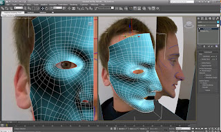
Once the head itself had been produced, I was now able to focus on creating and defining features such as eyes, lips and nostrils. I first looked at the nose, and as there were holes where the nostrils were meant to be, I selected the inner edges and held down shift and dragged the duplicate edges downwards. I made a few amendments to the edges' positions in order to make the nostril area look more realistic. I then had to cut up the polygons in order to make them into quadrants.
As there was still a hole where the nostril was I created another quadrant, but this time used the extrude polygon tool giving it a negative value. The final thing to do on the nostril area was to position them correctly in relation to the nasal cavity.

Next on the agenda were lips. I found these fairly tricky to manipulate. I created these by using the create polygon tool. Once all the polygons were created welded the vertices and then placed them into the appropriate positions by moving each vertex respectively. As you can see from the screenshot below, they do look very good and I am extremely pleased with the way they have turned out.

The most difficult thing so far is definitely getting the eyelids to look realistic. These took about 4 different times until I got a creation that I was happy with. I used the same technique as I used on the nostril in order to create the lids. As you can see from the image below I created another 2 loops of quadrants.

Throughout the creation of all these features I was using the original side of the face as anything I did on this side occurred on the other side of the mirror.

Thursday, 7 October 2010
Week 2 Modelling the Head
Using the 3Ds max file i created previously I was able to begin creating the model of my head. I started off by selecting the line tool and in the front view port i was able to click on the quadrants of the reference plane. Once a complete spline (in this case each quadrant) was formed i clicked yes to close spline.
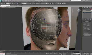
I did this over the entire face, and once this was complete I selected one of the newly formed quadrants. In order to convert a space into a editable surface I clicked on "convert to editable poly". In order to convert all the quadrants into this form, I scrolled down to the "attach" button and selected all of the lines. The obvious problem that I had at this point was that the surface was completely flat. In order to resolve this i began by selecting all of the vertices along the vertical centre line of, I then aligned them to the X axis, this made the centre line perfectly straight and would make it easier to mirror at a later stage. At this stage all the quadrants are seperate and independant sections at the moment (in other words at each corner of a quadrant there are 2 vertices). In order to join them all up together i selected all vertices and clicked on the small box next to "weld". This brought up a small dialogue box and with that i was able to select the appropriate threshold for which the vertices joined together.
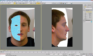
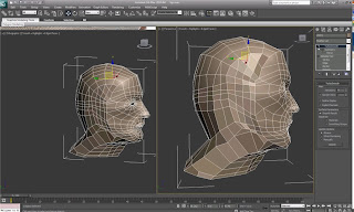
Still in the front viewport i selected all the vertices to the far right. Once these were selected I moved over to the left viewport and pulled them all out to their respected positions by lining them up to the reference plane. I then carried on doing this until i had all the vertices in the correct place other than the eye (as this was the trickiest part). As you can see in the turbo-smoothed image below the eye socket still needs a little work in order for it to be representive of my face.
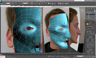
After a while of manipulating my eye and cheek bone i was able to create a model of my head that i was happy with. I realised that the cheek bone needed to cbe pulled out a little more in order to fill out the face, this also made the eye socket look flush as apposed to sticking out alien-esque.
When mirroring my face i did it with the x-axix. As this is the axis that goes vertically down the face. When cloning the side of the face i did this as a reference because the clone will always do what you do on the original, but not the other way round. Once the cloned had been created i moved it slightly to the left in order for it to match up with the other side of the face.


I did this over the entire face, and once this was complete I selected one of the newly formed quadrants. In order to convert a space into a editable surface I clicked on "convert to editable poly". In order to convert all the quadrants into this form, I scrolled down to the "attach" button and selected all of the lines. The obvious problem that I had at this point was that the surface was completely flat. In order to resolve this i began by selecting all of the vertices along the vertical centre line of, I then aligned them to the X axis, this made the centre line perfectly straight and would make it easier to mirror at a later stage. At this stage all the quadrants are seperate and independant sections at the moment (in other words at each corner of a quadrant there are 2 vertices). In order to join them all up together i selected all vertices and clicked on the small box next to "weld". This brought up a small dialogue box and with that i was able to select the appropriate threshold for which the vertices joined together.

Still in the front viewport i selected all the vertices to the far right. Once these were selected I moved over to the left viewport and pulled them all out to their respected positions by lining them up to the reference plane. I then carried on doing this until i had all the vertices in the correct place other than the eye (as this was the trickiest part). As you can see in the turbo-smoothed image below the eye socket still needs a little work in order for it to be representive of my face.


After a while of manipulating my eye and cheek bone i was able to create a model of my head that i was happy with. I realised that the cheek bone needed to cbe pulled out a little more in order to fill out the face, this also made the eye socket look flush as apposed to sticking out alien-esque.

When mirroring my face i did it with the x-axix. As this is the axis that goes vertically down the face. When cloning the side of the face i did this as a reference because the clone will always do what you do on the original, but not the other way round. Once the cloned had been created i moved it slightly to the left in order for it to match up with the other side of the face.

Wednesday, 29 September 2010
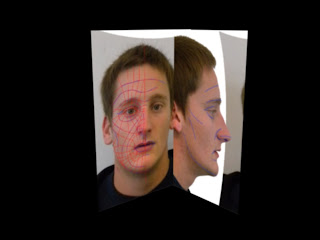
Week 1 Photoshop
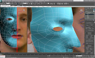
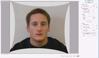
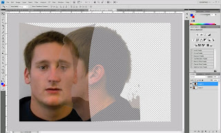
During the first week of this module we all had our mug-shots taken. These consisted of a frontal and a profile image. The images were then put through the "lens correction" filter within Photoshop. This enabled me to straighten up the images by lining up my ears, eyes and points of the lips. Once this was done, i removed the distortion by removing the fish-eye effect. Both original images were put through the lens correction filter.
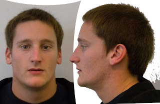
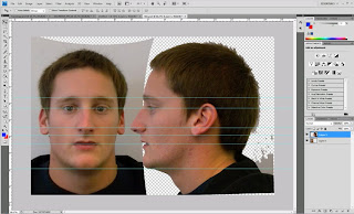
I then put the images onto the same file, but different layers. The enabled me to line up my face straight on and from the side. I did this by changing the opacity of the profile image down to about 60% and placed it upon the portrait image, a small amount of resizing and manipulation was required but, once the mouth, eye and nose were aligned i held down shift and moved the profile image back to the side. To make sure that the alignment was correct i used the guidelines that photoshop provided. I lined up my ears, eyes, nose, lips and eyebrows.
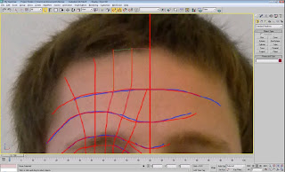
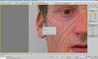
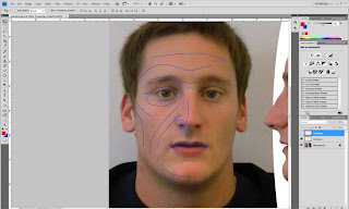
Once this was done i can start drawing on the countours of my face. I did this by selecting a blue brush with a thickness of about 3. I went over any creases, or deep facial features. This provided the main outline for my facial topology.
The topology was created out of a thin red brush - thickness of about 2. When doing this i had to make sure that i divided my face up into quadrants if there were any sections without 4 edges it would not work correctly. There is one vital quadrant within this topology, it is situated just below the eye socket and is a diamond. This is a directional changing quad.
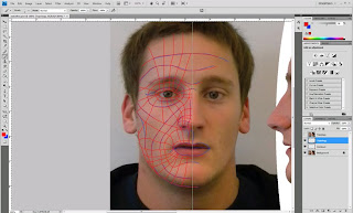
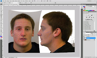
Once my entire face was split up into quadrants, i drew on the contours of the profile image. Now this was complete i put the portrait image of my face onto a plane within 3Ds Max. Lastly i put the profile image onto a plane of the same size. These will be used for reference planes when creating my 3D head model.


I then put the images onto the same file, but different layers. The enabled me to line up my face straight on and from the side. I did this by changing the opacity of the profile image down to about 60% and placed it upon the portrait image, a small amount of resizing and manipulation was required but, once the mouth, eye and nose were aligned i held down shift and moved the profile image back to the side. To make sure that the alignment was correct i used the guidelines that photoshop provided. I lined up my ears, eyes, nose, lips and eyebrows.


Once this was done i can start drawing on the countours of my face. I did this by selecting a blue brush with a thickness of about 3. I went over any creases, or deep facial features. This provided the main outline for my facial topology.

The topology was created out of a thin red brush - thickness of about 2. When doing this i had to make sure that i divided my face up into quadrants if there were any sections without 4 edges it would not work correctly. There is one vital quadrant within this topology, it is situated just below the eye socket and is a diamond. This is a directional changing quad.


Once my entire face was split up into quadrants, i drew on the contours of the profile image. Now this was complete i put the portrait image of my face onto a plane within 3Ds Max. Lastly i put the profile image onto a plane of the same size. These will be used for reference planes when creating my 3D head model.

Subscribe to:
Posts (Atom)